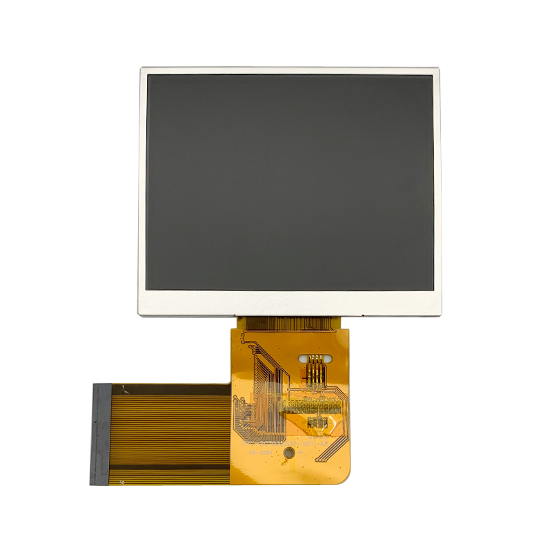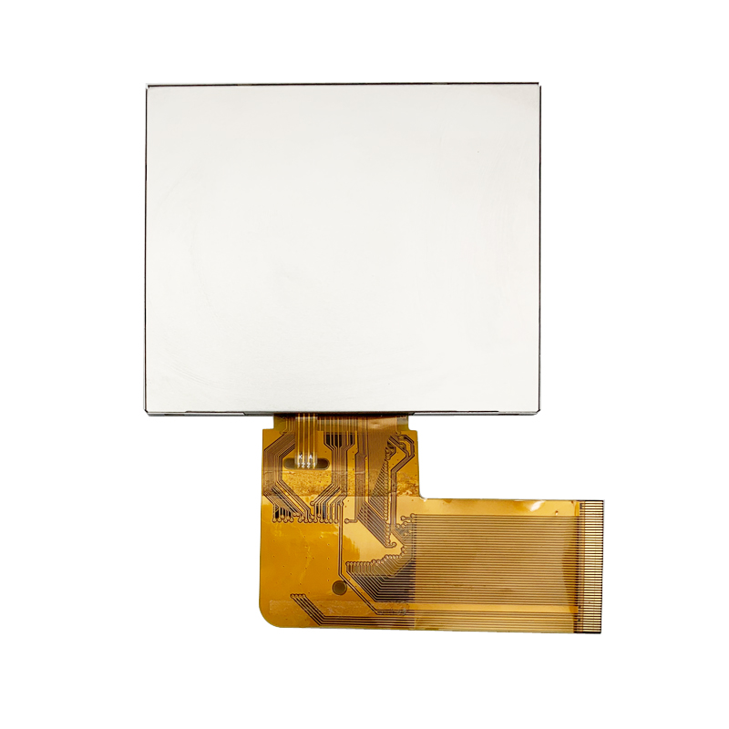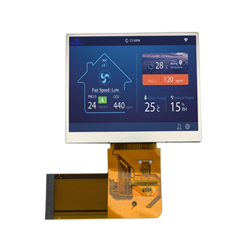


General Specification
| Item | Nominal Dimension | Unit |
|---|---|---|
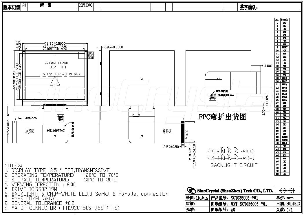
| Dot Matrix | 320 x RGB x 240 | Dots |
| Module Size ( W×H×T ) | 76.90 x 63.90 x 3.05 | mm. |
| Active Area ( W×H ) | 70.08 x 52.56 | mm. |
| Pixel arrangement | RGB Stripe | mm. |
| Dot Pitch ( W×H ) | 0.219 x 0.219 | mm. |
| Color depth | 262K(MAX) | colors |
| Interface | MCU & RGB | – |
| Driving IC Package | COG | – |
| Operating temperature | -20 ~70 | ºC |
| Storage temperature | -30~80 | ºC |
| LCD Type | a-Si TFT | – |
| LCD Mode | TN/Normal White | – |
| Backlight Type | LED x 6 | PCS |
Interface Definition
| Pin No | Pin Symbol | Level | Description |
|---|---|---|---|
| 1 | GND | 0V | Ground |
| 2–3 | NC | – | No use |
| 4–6 | GND | 0V | Ground |
| 7 | RD | H/L | 6800-system: E(enable signal) 8080-system : RD (read strobe signal) |
| 8 | SDO | H/L | Data output pin in serial interface |
| 9 | RESET | H/L | Reset signal |
| 10 | CS | H/L | Chip Select |
| 11 | SCL | H/L | Serial clock input |
| 12 | SDA | H/L | Data input pin in serial interface |
| 13 | RS | H/L | selector of command or parameter |
| 6800-system : RW (indicates read cycle when High, write cycle when Low) | |||
| 14 | WR | H/L | 8080-system : WR (write strobe signal) |
| 15 | PS3 | H/L | Detail see below picture |
| 16 | PS2 | H/L | |
| 17 | PS1 | H/L | |
| 18 | PS0 | H/L | Data bus , Fix to VSS level when not in use |
| 19-36 | DB17 – DB0 | H/L | When 16-bit be selected, D[17:10] and D[8:1] used |
| 37 | DEN | H/L | Display enable pin from controller. |
| 38 | VSYNC | H/L | Frame/Ram Write Synchronization input |
| 39 | HSYNC | H/L | Line Synchronization input |
| Dot-clock signal and oscillator source. A non-stop external | |||
| 40 | DCLK | H/L | clock must be provided to that pin even at front or black porch non-display period. |
| 41 | NC | – | No use |
| 42-43 | GND | 0V | Ground |
| 44-45 | VDD | 2.8-3.3V | Power supply |
| 46 | NC | – | No use |