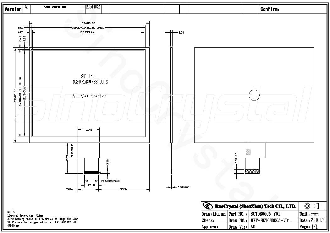


General Specification
| Item | Standard value | Unit |
| LCD Size | 8 | inch |
| Dot Matrix | 1024(RGB) × 768 | pixel |
| Module Size | 174.00 × 136.00 × 2.45 | mm |
| Active Area | 162.05 × 121.54 | mm |
| Dot Pitch | 0.15825 × 0.15825 | mm |
| Pixel Configuration | R.G.B. Stripe | – |
| Color depth | 16.7M | – |
| Display Mode | Normally Black, Transmissive | – |
| Technology Type | a-Si | – |
| Viewing Direction | All | – |
| Gray Scale Inversion Direction | All | – |
| Driver IC | TBD | – |
| Interface | LVDS | – |
| LED Numbers | 33 LEDs | – |
| Weight | TBD | g |
Interface Definition
| Pin No. | Symbol | Type | Description |
| 1 | VCOM | P | Common Voltage |
| 2 | VDD | P | Power Voltage for digital circuit |
| 3 | VDD | P | Power Voltage for digital circuit |
| 4 | NC | – | No connection |
| 5 | Reset | I | Global reset pin |
|
6 |
STBYB |
I | Standby mode, normally pulled high STBYB = “1”, normal operation STBYB = “0”, timing controller, source driver will turn off, all output are High-Z |
| 7 | GND | P | Ground |
| 8 | RXIN0- | I | – LVDS differential data input |
| 9 | RXIN0+ | I | + LVDS differential data input |
| 10 | GND | P | Ground |
| 11 | RXIN1- | I | – LVDS differential data input |
| 12 | RXIN1+ | I | + LVDS differential data input |
| 13 | GND | P | Ground |
| 14 | RXIN2- | I | – LVDS differential data input |
| 15 | RXIN2+ | I | + LVDS differential data input |
| 16 | GND | P | Ground |
| 17 | RXCLKIN- | I | – LVDS differential clock input |
| 18 | RXCLKIN+ | I | + LVDS differential clock input |
| 19 | GND | P | Ground |
| 20 | RXIN3- | I | – LVDS differential data input |
| 21 | RXIN3+ | I | + LVDS differential data input |